Experiment
TD1002A

LINEAR HEAT CONDUCTION EXPERIMENT
An experimental module to introduce students to the principles of linear heat conduction, and to allow the thermal conductivity of various materials to be measured.
If you have any questions or you'd like to discuss a product, please call us.
+44 1159 722 611LINEAR HEAT CONDUCTION EXPERIMENT
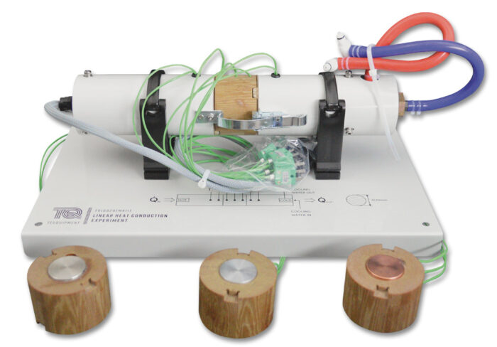
This experiment has a solid brass bar of circular crosssection, made in two sections with an interchangeable middle section. It mounts on a base plate with a clear schematic of the experiment layout. The first brass section includes two thermocouples and the electric heater (heat source). The second brass section includes a small watercooled chamber (heat sink) and two more thermocouples. The interchangeable middle sections (supplied) are of different metals:
• Brass – so the bar becomes one length of brass
• Aluminium
• Stainless steel
• Copper
Each middle section has three thermocouples to enable the calculation of thermal conductivity of specimens using two different methods:
• The absolute method
• The comparative cut-bar method
The electric heater and thermocouples connect to sockets on the Heat Transfer Experiments Base Unit, which also supplies the cold water feed and drain for the heat sink.
Students turn on the cooling water flow and adjust the heater power until the experiment reaches equilibrium they then record the temperatures as the heat conducts along the bar. Insulation around the bar reduces heat loss by convection and radiation, so that the results should be close to the theory for simple linear conduction only. (Heat loss can also be simply estimated using a pre-determined
TecQuipment chart and table).
Learning outcomes
- Demonstration and calculations of linear heat conduction
- Calculation of the thermal conductivity (k value)
- Demonstration of the effectiveness of thermal paste
- Demonstration and calculations of thermal resistances (R value) in series
- Demonstration of ‘thermal lag’


