Experiment
AF41V

FLIGHT DEMONSTRATION WIND TUNNEL
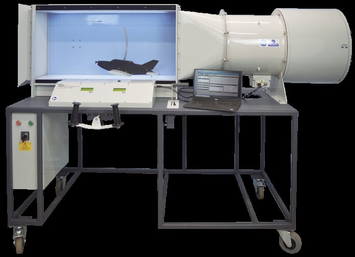
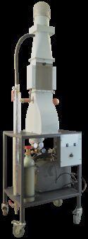
A model aircraft suspended in an open circuit wind tunnel. Includes realistic fly-by-wire flight controls to simulate a variety of principles of aircraft flight.
If you have any questions or you'd like to discuss a product, please call us.
+44 1159 722 611FLIGHT DEMONSTRATION WIND TUNNEL
For classroom demonstrations and student investigations into the behaviour of fixed-wing aircraft and wing performance during take-off, flight and landing.
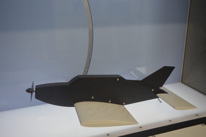
The apparatus is an open-circuit wind tunnel with a model aircraft suspended in the working section. The model is supported by linkages that allow it to move vertically and to pitch about the quarter chord point independently.
The working section is LED illuminated and the aircraft model is clearly visible through a large window. The operator flies the aircraft manually using a digital fly by wire control column and throttle. These are positioned directly in front of the window and are arranged as typically found in a light aircraft, providing realistic simulation of flight and the effect of the control surfaces.
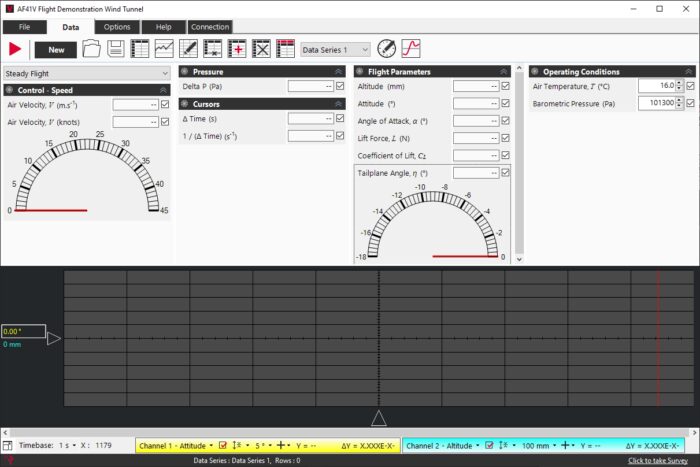
To fly the aircraft, the operator uses the throttle lever to increase the tunnel airspeed. When the airspeed reaches a certain level the aircraft may be made to ‘take-off ’ by drawing the control column slowly back. A digital display shows Pitot pressure (air velocity) in the working section, attitude, altitude or lift force on the aircraft along with tail plane angle.
Air enters the working section through a flow straightener. The throttle controls the air speed in the tunnel by regulating an axial flow fan downstream of the working section. The change in air speed in the wind tunnel simulates the effect of increasing the change in air speed of a real aircraft due to a change in thrust from the propeller.
The control column is linked to the ‘all-flying’ tailplane of the aircraft. Pushing the column forward or pulling it back changes the angle of the whole tailplane. The control column differs from that of a normal aircraft in that it has no lateral control of the aircraft: it has no rudder on the tailplane and may only move up or down.
A locking control under the control column can lock the angle of the tail plane to any setting.
Small tufts cover the port wing of the aircraft. These show the direction and quality of airflow over the wing surface, to show separation and stall. Using the optional Smoke Generator (AFA11, available separately) enhances flow visualisation.
An adjustable weight allows the student to set the centre of gravity of the model to different positions from fore to aft of the quarter chord point. A scale below the weight indicates the position. This enables students to derive the trim curves and identify the neutral point.
To find the lift characteristic of the aerofoil, students link the aircraft to a load cell and vary the angle of attack.
Learning outcomes
A variety of practical demonstrations, ‘hands-on’ flight simulations and student investigations into the behaviour of fixed-wing aircraft and wing performance, including:
- Practical investigation of longitudinal stability and control of the aircraft to demonstrate behaviour during take-off , level flight and landing.
- Determination of the effect of speed on attitude for level flight and stall.
- Measurement of the lift curve for the wing up to and beyond stall.
- Students can adjust the centre of gravity of the model to alter its trim. They can then plot trim curves and determine the neutral point.
- Demonstration of phugoid motion in terms of altitude via high speed VDAS®.
- Short period oscillation due to sudden disturbance can be shown by the change of incidence via high speed VDAS®.
With Smoke Generator and Probe (AFA11, avaiable separately):
- Visualisation of flow patterns past the aircraft’s aerofoil and tail-plane.

