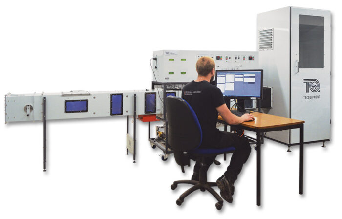
Base Unit
EC1550V

Advanced HVAC & R Trainer
A versatile, floor-standing unit for the in-depth study of heating, ventilation, air conditioning and refrigeration (HVAC & R) systems.
If you have any questions or you'd like to discuss a product, please call us.
+44 1159 722 611Advanced HVAC & R Trainer
The EC1550V has two distinct systems – these are commonly known as an air handling unit and a water chiller. The air handling unit conditions the air by using one or more air processes.
The water chiller cools the water in the tank so it can be pumped to the water-to-air heat exchanger in the air handling unit to provide sensible cooling or combined cooling and dehumidification. The unit is fitted with lights and windows so that the components of each air process can be clearly identified.
At the end of each air process, a temperature and humidity sensor is provided so that the performance of the process can be tested individually as well as collectively.
The control panel allows the adjustment of key components such as air flow velocity, temperature and water flow rate, allowing performance comparisons at different set points. Furthermore, it offers VDAS® connectivity, a USB cable (supplied) connects the unit to a suitable PC (not supplied) running TecQuipment’s VDAS® software that captures, records and displays data.
The inlet of the unit is covered by a grille and air filter for safety and air quality, followed by a variable-speed axial fan providing a maximum of 1200 m3.h-1 of air to its outlet.
The first psychrometric process is sensible heating and this is achieved via a 1.5 kW PID controlled electric heater.
The next subsystem is a steam humidifier followed by a 300 mm x 300 mm water-to-air heat exchanger that provides dry cooling to the air stream. The next subsystem along the stream is the air washer. It uses water pumped at high pressure (60 psi) through misting nozzles. Water is supplied from the chilled water tank so experiments can be performed with either water at room temperature or chilled. The final component in the main duct is a 1.5 kW PID-controlled electric re-heater.
Contained on the bottom shelf of the unit is a complete refrigeration system. The refrigerant R134-a cools the water in the tank. The chilled water serves two purposes within the unit. Primarily, it cools the air via the water-to-air heat exchanger. Additionally, it provides chilled water to the air washer, enhancing the experiment’s range.
The core components of the refrigeration unit are the high back pressure condensing unit, the thermostatic expansion valve and the helicoidal evaporator contained inside the water tank. In addition, other components such as a suction line accumulator, filter dryer, liquid receiver, pressure switches and rotolock service valves are incorporated for safety, maintenance and to prevent damage to the unit.
The refrigeration cycle includes high and low-pressure gauges and transducers, thermocouples on each line, a refrigerant flow meter and a Watt transducer allowing students to analyse the performance of the cycle and compare experimental results and calculations with theory.
Learning outcomes
Air Handling Unit
• Investigation of psychrometrics, definitions, relations and psychrometric charts
• Understanding of an air handling unit’s electromechanical components and their function
• Investigation of psychrometric processes including:
Single Stage Processes
a) Sensible heating
b) Sensible cooling
c) Sensible and latent cooling and dehumidification
d) Adiabatic humidification (evaporative cooling via air washer)
e) Steam humidification
Multiple Stage Processes (typical Examples)
f) Heating and humidification
g) Cooling and humidification
h) Cooling, humidification and heating
• Observation of the effect of varying the fan speed, pump flow rates and temperature settings for all the above psychrometric processes and combinations
• Calculation of the sensible heat ratio and dew point
• Evaluation of the heat transfer across the water-to air heat exchanger and the log mean temperature difference (LMTD) driving force
• Determination of the mass flow and
Water Chiller
• Understanding of refrigeration components and their function
• Investigation of the vapour compression refrigeration cycle including:
– Real-time plotting of the P-h thermodynamic cycle for refrigerant R134a
– Calculation of superheat, subcooling, pressure ratio, saturated evaporating temperature and saturated condensing temperature
– Calculation of the isentropic efficiency of the compressor
– Calculation of the heat balance, mass flow rate and theoretical power of the saturation cycle
– Understanding the effect of suction temperature and condenser temperature on the refrigeration effect and CoP
– Calculation of the effect of varying the load on the refrigeration cycle
• Determination of the mass flow and energy balance across the refrigeration cycle


